Platform / AcaysiaGEM
Geometry engine
AcaysiaGEM
A spatial simulation is only ever as good as the shape you run it in.
Real vessels are not boxes — they have dished bottoms, baffles, downcomers, sparger rings and nozzles set at awkward angles, and every one of those changes the answer. GEM builds that shape, proves it is fit to simulate before a GPU hour is spent on it, and hands it to AcaysiaDRT ready to run.
- Geometry library
- 18
- Parametric geometries, benchmark duct to full vessel
- Boundary tags
- 100%
- Boundary faces tagged, or the build fails
- Wasted GPU hours
- 0
- On a leaking domain
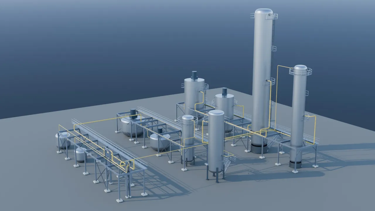
The model is the picture
Rendered from the solver's own geometry
Not a picture of a plant — the plant itself.
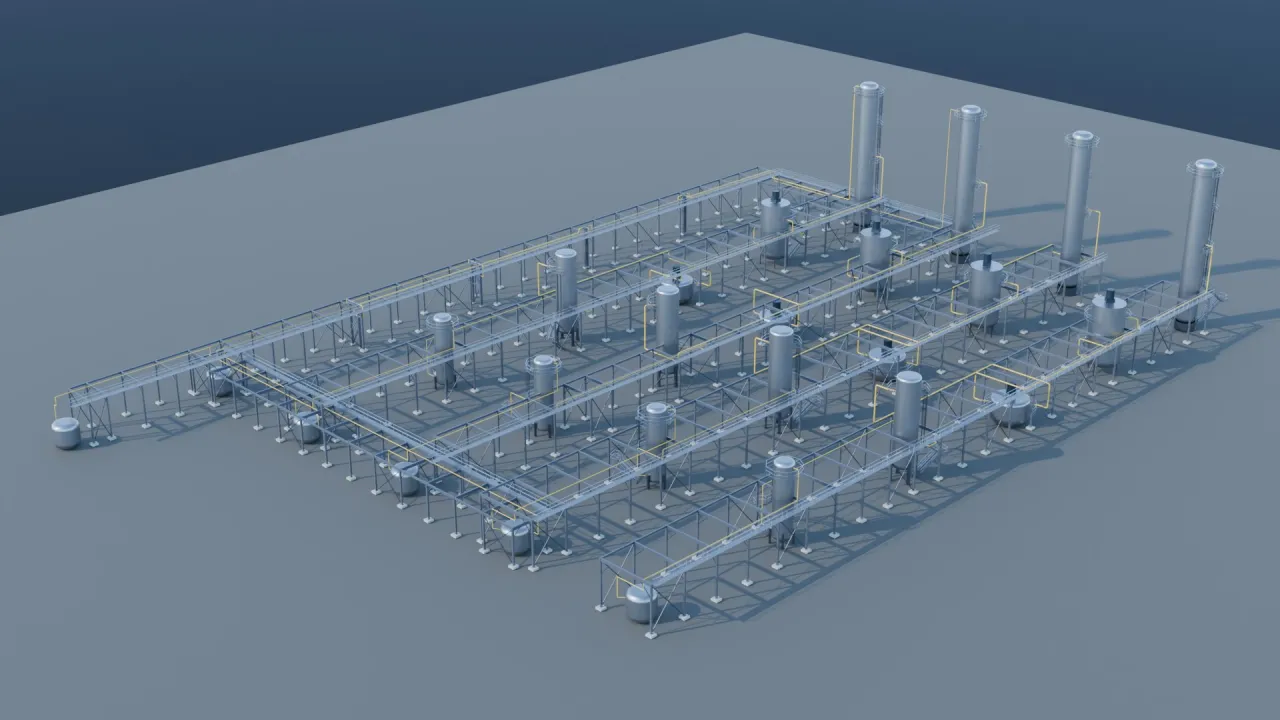
Twelve units, routed lines and procedural steel.
Authored parametrically and rendered straight from the same model the solver runs on. There is no separate marketing model to fall out of sync — when the design changes, the picture changes with it.
-
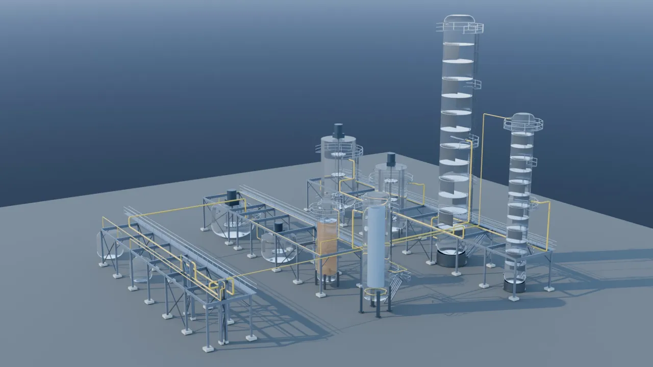
Two looks
Equipment, or x-ray.
One scene rendered twice. Nothing was modeled specially for the transparent version — the internals were always in the geometry, because the solver needs them there.
-
Fast
Seconds, not hours.
The twelve-unit plant renders in about 6 seconds on a GPU. Fast enough that a render is something you do while iterating, not a deliverable you schedule a day for.
-
Web-native
Ship the model, not a screenshot.
Output is a still image, an editable scene, or a 3D file a browser can open — usually the better answer, since it is the model itself rather than a picture of it.
-
Composable
Drops onto a page.
Renders come out on transparent backgrounds with the plant still standing on its own shadow, so it composites cleanly onto whatever sits behind it.
The idea
Fluid domain · tagged negative space
Model the space,
not the steel.
Ordinary CAD describes the vessel: the shell, the flanges, the weld prep. A solver does not care about any of that. It cares about the shape of the liquid.
GEM models that negative space directly, and labels its edges as it builds them. That is why its output drops into a solver without the usual translation losses.
Internals
What the solver sees, and what it doesn't.
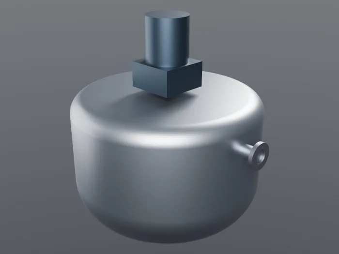
Agitator shafts, turbines, drive motors, baffles and nozzle flanges can be carried for visual fidelity without polluting the physics. A rotating impeller is handed to the solver as the volume it sweeps, which is the honest representation of it.
Geometry library
18 geometries · 3 families
Eighteen shapes, three families.
From the ducts the solver is benchmarked on to the real equipment, internals and all.
| Family | Geometries | What it is for |
|---|---|---|
| Flow domains6 | Channel · cylinder in channel · backward-facing step · sudden expansion · serpentine mixer · lid-driven cavity | Benchmark ducts — the shapes the solver is benchmarked on, where an analytic or published answer exists. |
| Inline components2 | Tee mixer · orifice plate | Round pipe fittings — blending at a junction, and pressure loss across a restriction. |
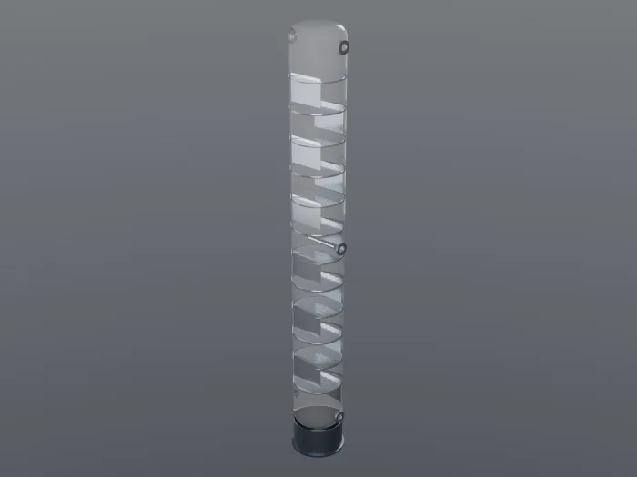
| Vessels10 | Stirred tank · distillation column · bubble column · packed-bed reactor · fermenter · flash drum · decanter · cyclone · drum · horizontal separator | The real equipment — internals and all, at the scale a plant actually runs. |
Parameter sweeps
Each geometry sweeps across its whole parameter range in the test suite, so a mis-tagged large impeller, a baffle poking through a dished bottom, or an unsealed vessel is caught automatically on any change — not discovered halfway through a run.
Process · the export is gated
Describe · Build · Check · Export
How a domain gets built.
Describe it, build it, check it, export it — nothing reaches the solver until the check has passed.
Each step exists because the alternative fails quietly rather than loudly.
-
Describe · Parametric
Dimensions, not drawings.
A vessel is described by the numbers an engineer already has — diameter, liquid height, impeller ratio, clearance, nozzle positions — and rebuilt from them on demand. Changing a design means changing a number, not redrawing a model.
-
Build · Tagged at build
The builder knows what it built.
Boundary faces get their meaning — inlet, outlet, wall, symmetry, exclusion — at the moment the builder creates them. No fragile post-hoc guessing about which surface was the inlet, and no selector language to get wrong.
-
Check · Health check
Fail on the desk.
Watertight, every face tagged, one connected fluid, nothing protruding. Every domain has to pass its health check before it can be exported — the four checks.
-
Export · Lattice-ready
Straight into the solver.
A validated domain converts into exactly what AcaysiaDRT consumes, in the solver's own conventions — no translation losses.
Step 03 · Health check
Runs before every export
Fail on the desk, not on the cluster.
The expensive failure in spatial simulation is not a wrong answer.
It is a run that consumes a night of GPU time and produces nonsense because the domain leaked. Every GEM domain has to pass a health check before it can be exported.
-
Watertight
A real solid.
Valid, watertight, a single connected body with positive volume. The check that catches a geometry which merely looks closed on screen.
-
No untagged faces
Every boundary has a rule.
Each boundary face must carry exactly one tag. An untagged face is a hole in the physics — a boundary the solver has no instruction for — and it leaks silently rather than erroring.
-
Nothing stranded
One connected fluid.
The fluid must be one region with no isolated pockets, every declared opening must actually reach it, and the domain must be sealed everywhere an opening does not exist.
-
Nothing protruding
Internals stay inside.
Anything declared as submerged has to genuinely sit within the fluid. When it doesn't, the check names the offending point rather than leaving you to find it in a render.
Grounded
Checked against real CAD.
Where a trusted reference part exists, GEM's model is regression-checked against it, so a simplified flow domain stays honest about the equipment it represents.
Step 04 · Export
Build · check · hand off
Straight into the solver.
Build, check, hand off. Every domain has to pass its health check before it reaches the solver.
- Export
- Lattice-ready, three ways. A validated domain converts into exactly what the solver consumes. Where a geometry carries an exact mathematical description of its surface, the export uses it, giving sub-cell accuracy at curved walls instead of a staircase.
- Contract
- No translation losses. The export encodes the solver's own conventions directly, pulled from its source rather than reimplemented — the class of mismatch that produces a simulation which runs happily and means nothing.
- Downstream
- Then it's a DRT run. From there it is an AcaysiaDRT job: solved flow, transport, and the chemistry that AcaysiaRT supplies per cell.
- In the app
- Without the toolchain. AcaysiaCORE brings this into the browser — pick a geometry, set the parameters, see it in 3D, check the regions, and export it for a run without installing anything.
Channel · 100 × 20 × 20 mm · as the solver receives it
Schematic
- Fluid
- Wall · solid
- Inlet
- Outlet
Health check · before export
- Watertight
- Every face tagged
- One connected fluid
- Nothing protruding
Plant assembly
The physical counterpart of a Rete flowsheet
One vessel is the primitive.
A plant is the point.
The same machinery that places one vessel places thirty of them.
GEM grows from independent geometries into a laid-out, connected, named plant.
-
Plot plan
Place and orient.
Units are positioned as a plot plan, each placed unit carrying its boundary tags along with it — the detail that separates a real assembly from a pile of shapes that lost their meaning when they moved.
-
Piping
Routed, not drawn.
Connections between units are routed through the plant as real line work rather than sketched, with nozzle-to-nozzle port matching and collision awareness.
-
Structure
Racks, steel and access.
Pipe racks, supports and access structure come with it, so what you are looking at reads as a plant rather than as vessels floating in space.
-
Cheap by design
Thirty units, eight builds.
Identical units share one underlying shape, so a thirty-unit plan costs eight builds and not thirty. That is what makes assembling a whole plant routine instead of an overnight job.
AcaysiaGEM
Geometry → AcaysiaDRT
Start from your geometry.
Talk to us about modeling your vessels — and what changes when the simulation runs in the real shape instead of an idealized one.
Book a discovery call